Work in progress: OPEN THE BOLEX: Difference between revisions
| Line 182: | Line 182: | ||
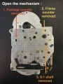
1. Remove footage counter + washer | 1. Remove footage counter + washer | ||
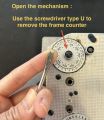
2. Remove frame counter (using type U screwdriver). Pay attention: it contains many little elements: a washer, shaft and cog wheel | 2. Remove frame counter (using type U screwdriver). Pay attention: it contains many little elements: a washer, shaft and cog wheel, and two washers below that could stick to the base plate, pay attention. | ||
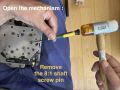
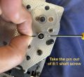
3. Remove the 8/1 shaft button. For this you need to gently hit the small locking pin with a small screwdriver and little hammer (see picture). Pay attention to the little elements: the pin, and a spring washer and washer on top that are kept in position by the pin when reassembling | 3. Remove the 8/1 shaft button. For this you need to gently hit the small locking pin with a small screwdriver and little hammer (see picture). Pay attention to the little elements: the pin, and a spring washer and washer on top that are kept in position by the pin when reassembling | ||
Revision as of 13:17, 25 October 2026
open the BOLEX introduction
Manuals
How to use
who we are
series number vs camera model
https://www.bolexcollector.org/cameras
index
A_Pressure-Pad-Blade
B_Claw
C_Turret


Turret check
There must be no misalignment between the base and the turret. Some turrets are bent because the lens is too heavy. C-Mount RX lenses, when focused at infinity, produce a sharp image 17.5mm beyond the end of the thread. Always use RX lenses for Bolex Rex cameras, as other lenses produce a sharp image at 15mm. These can only be used when filming close up (not at infinity).
D_Variable shutter
E_Camera body
F_Upper Base plate
G_Lower base plate
H_Motor spring Winding mechanism
IT_Mechanism
J_Frame counter
K_Speed governor
L_Loop-former
M_Lid-Rewinding handle
N_Leathering
O_Viewfinders
P_Eye-level focus
Q_RX-Viewfinder
Shutter timing
issues or trouble shooting
Basic check procedure
- Observe the outside aspect of the camera.
- Check the prism, if there are any scratches or fingerprints.
- Check shutter timing
- Check spring motor:
- put on 24fps, run with different fps, but load a test film when you run with 48 or 64fps.
- Winding up more than 21 rounds
- Listen to the sound, if the sound slowing down, means the dust is inside the plate and dried out lubrication
- holding the take up, to see if the take up is running
- Check how many seconds is fully winded, between 24-27 seconds
- Check if the counter is working
- Check the turret if it is flat on the plate, if it is distorted, perhaps by heavy lens
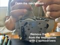
Open the mechanism
00
01
02
03
04
05
06
07
08
09
10
11
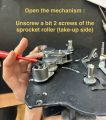
12
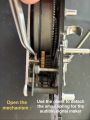
13
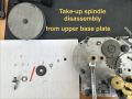
14
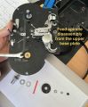
15
16
17
18
19
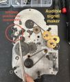
20
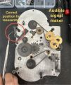
21
22
23
24
25
26
27
28
29
30


Opening procedure step by step
(1) Unwind the motorspring completely and take off the handle
(2) Take the Viewfinder off:
1.Four little screws for the cover
2.Close the reflex viewfinder closing lever
3.Four screws to take off viewfinder
(3) Take out pressure plate

(4) Take off Turret
1. First the screw of the lock, with a nut inside that takes no.6 wrench
2. Three other screws to take turret off
(5) Carefully take out the claw mechanism
1. Two little screws for the cover plate
2. One screw for the two claws with two washers in between (see picture). For this you need a 2.5 flat screwdriver. Pay attention to the order of the forward claw/washer/backward claw/spring washer
(6) Go to front Camera Body side to unscrew four screws (see picture)

1. Disengage Motor to 0 and take off lever
2. Take off I/T lever
3. Take off Speed dial
4. Take of Slide release button
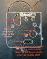
(7) To get the whole mechanism (upper & lower base plates) out, remove three screws on the low base plate (see picture)


(8) To take out the mechanism plates we need to use force.
1. The light seal makes the mechanism stick, to break it we need to slam it on the table with controlled force
2. The film cutter needs be pushed away
3. (The release button needs to be held out when reassembling)
(9) To prepare the disassembling of the two plates:
1. Remove footage counter + washer
2. Remove frame counter (using type U screwdriver). Pay attention: it contains many little elements: a washer, shaft and cog wheel, and two washers below that could stick to the base plate, pay attention.
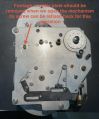
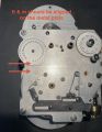
3. Remove the 8/1 shaft button. For this you need to gently hit the small locking pin with a small screwdriver and little hammer (see picture). Pay attention to the little elements: the pin, and a spring washer and washer on top that are kept in position by the pin when reassembling (Picture of plate after removal of the knobs)
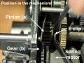
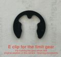
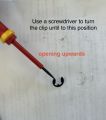
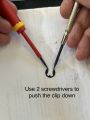
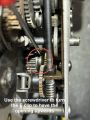
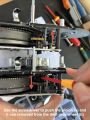
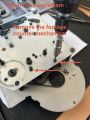
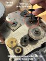
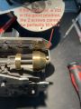
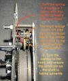
4. Release the limit gear (that stops the Motor spring at beginning and end) by removing the E clip (see picture). Carefully lift the pinion (a) from gear wheel (b) (see page page 187 of the manual) so the last tension of the spring motor will be released. Eventually release the four main connecting plate screws a bit to create space to wiggle the spring motor to release all the tension.
5. Remove footage counter drive gear with two screws
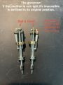
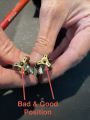
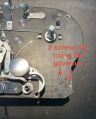
6. Remove the Governor by releasing the two screws of the bell.
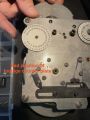
7. Remove the spring of the click mechanism (see picture)
8. Release two screws of the bottom sprocket (no need to remove)
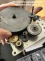
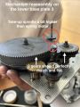
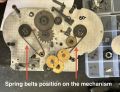
(10) Disassemble the two plates by releasing the four screws completely. Pay attention to the eventual washers that could drop or keep sticking to the plate!!!
(11) To lubricate the take-up spindle it’s possible to take it apart with wrench 6 & 8 (see pictures)